I love LED strip lighting. I first saw individually addressable LEDs on flexible strips in a Christmas tree decoration ca. 2011 and was sold. Since then, I’ve slowly worked on putting them to use in a smart DIY under-counter LED light system. Now, nearly 3 years after starting, I think I am getting closer! This post will be divided into at least 2 parts to describe the install and the electronics.
At the time I started this project, I really only had a few requirements:
- LEDs had to be individually addressable.
- Install had to be clean, i.e., I didn’t want any wires showing.
- Install had to be removable, i.e., I wasn’t willing to solder or permanently install anything more than 120V outlets.
With the first requirement, I discovered a myriad of options for LEDs, but quickly discovered I needed a digital strip rather than an analog one.1 I also discovered an amazing open source project called FastLED that supports almost all types of LEDs out there. My research led me to shift-register type SPI based LEDs (e.g., APA102), as opposed to timing dependent PWM types (e.g., WS2812B). I was hoping to maximize the number of LEDs and response times, and gravitated to APA102. This is a 5V, 4-wire chipset that is now deprecated and hard to get. I would love to get my hands on the newer NS107S LEDs to try them out. But I digress.
I purchased 4 x 5m reels of 30 LEDs/meter APA102 LEDs from Amazon and began my arduous task of hiding 486 LEDs along the top and bottoms perimeters of my cabinets. I selected LEDs that came in a silicon sleeve with 3M tape on the back.
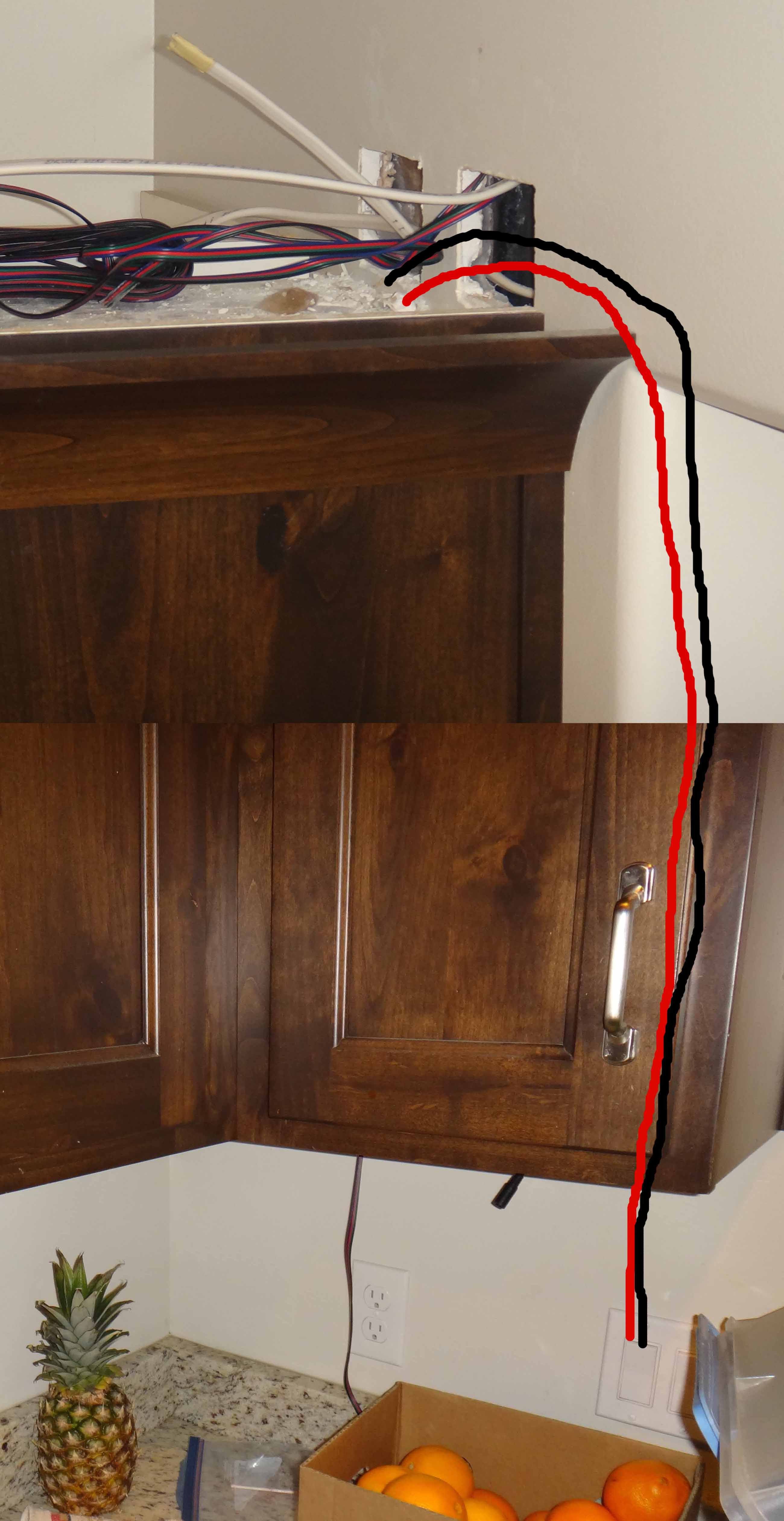
Because of the second and third requirements, I decided my first task was to add an AC outlet above each of my cabinet sections, all tied to a single switch. That way, if I ever just want to go back to normal lights on top, I can just plug them in and control them with the switch. I just tied into a light switch available under one of my cabinets, then ran new Romex up the wall to the top of the cabinet. Only worry about the nearest hole in the wall for now:
Another reason to run more than one AC outlet was that I was unsure how many 5V power supplies I would need and how spread out they would need to be to power my nearly 20m of strip LEDs. So I wanted to have enough to power both the top and bottom LEDs at any point along the path. If I had known how much time I would spend crawling around in my attic, I may never have finished!
After running my AC outlets (4 to be exact), I started working on the LED control wires. I used 4-conductor ribbon cable from Amazon to connect each section of my LED. Here is where I made the biggest mistake of my project. I skimped and went for 22AWG rather than 20 or even 18AWG. Because of the amount of crimping involved (see below), I can’t bear the thought of repeating it. But I still have occasional glitches in my LEDs at high brightness and high RGB intensity (max power draw), making me suspect this cable is the culprit.
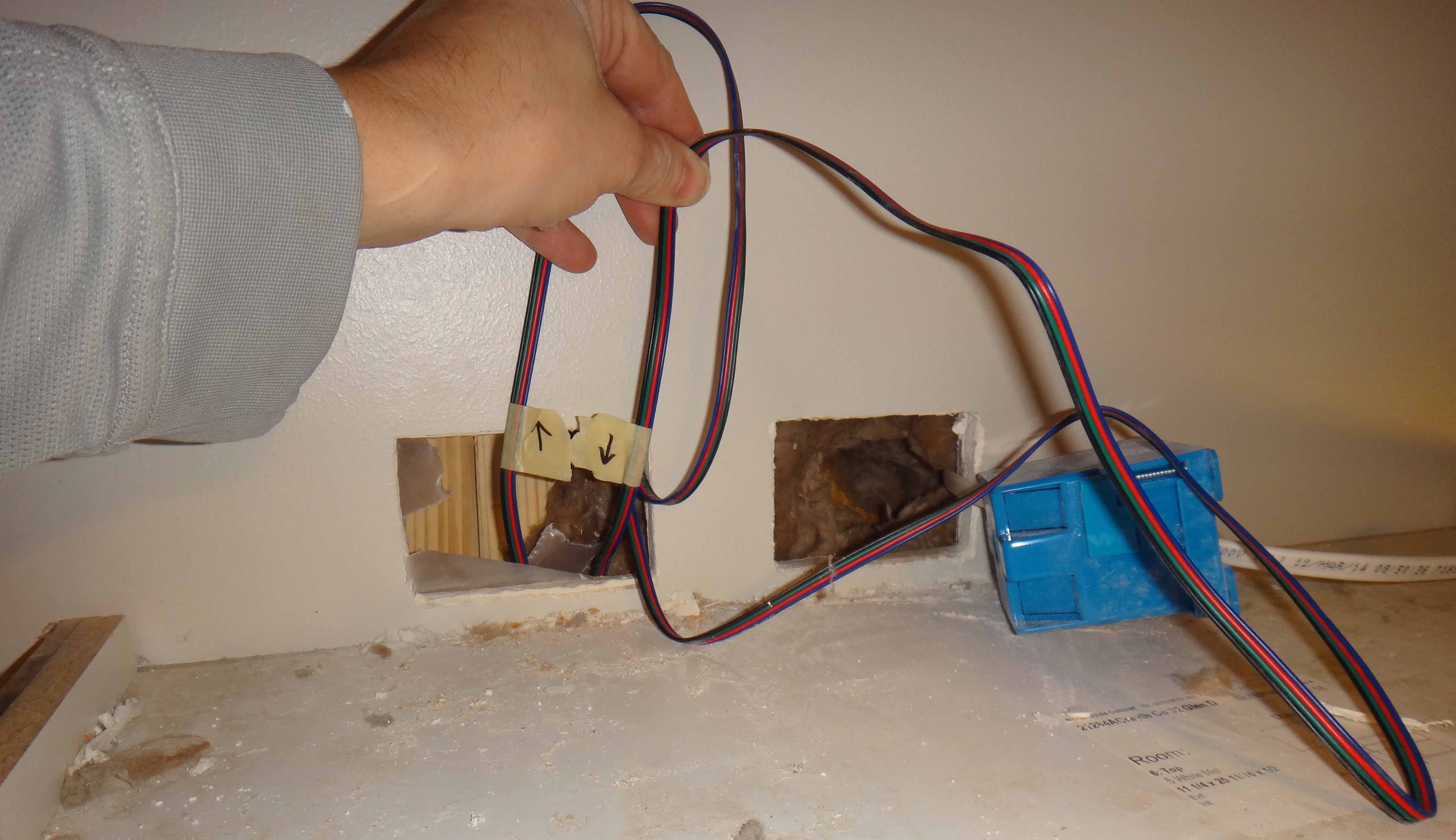
In the image above, you can see where I cut out a second junction box near my AC for my LED control wire. I decided to run all of my lights in series, as you can see in the GIF animation on top. So my first pixel is on the top of my left cabinet, works its way across the top of the middle cabinets, and then all the way to my right-hand cabinets, then works its way back along the bottom of the cabinets back to the left. So I had to connect all of those sections in serial with the control wire, again using the attic to go to different top sections of cabinets and the wall to go down to the bottom sections.
Coming out the bottom was harder, as I didn’t want to make large visible holes on the bottom. I just had to drill a small hole in cabinet and fish out a tape to pull the wire through.
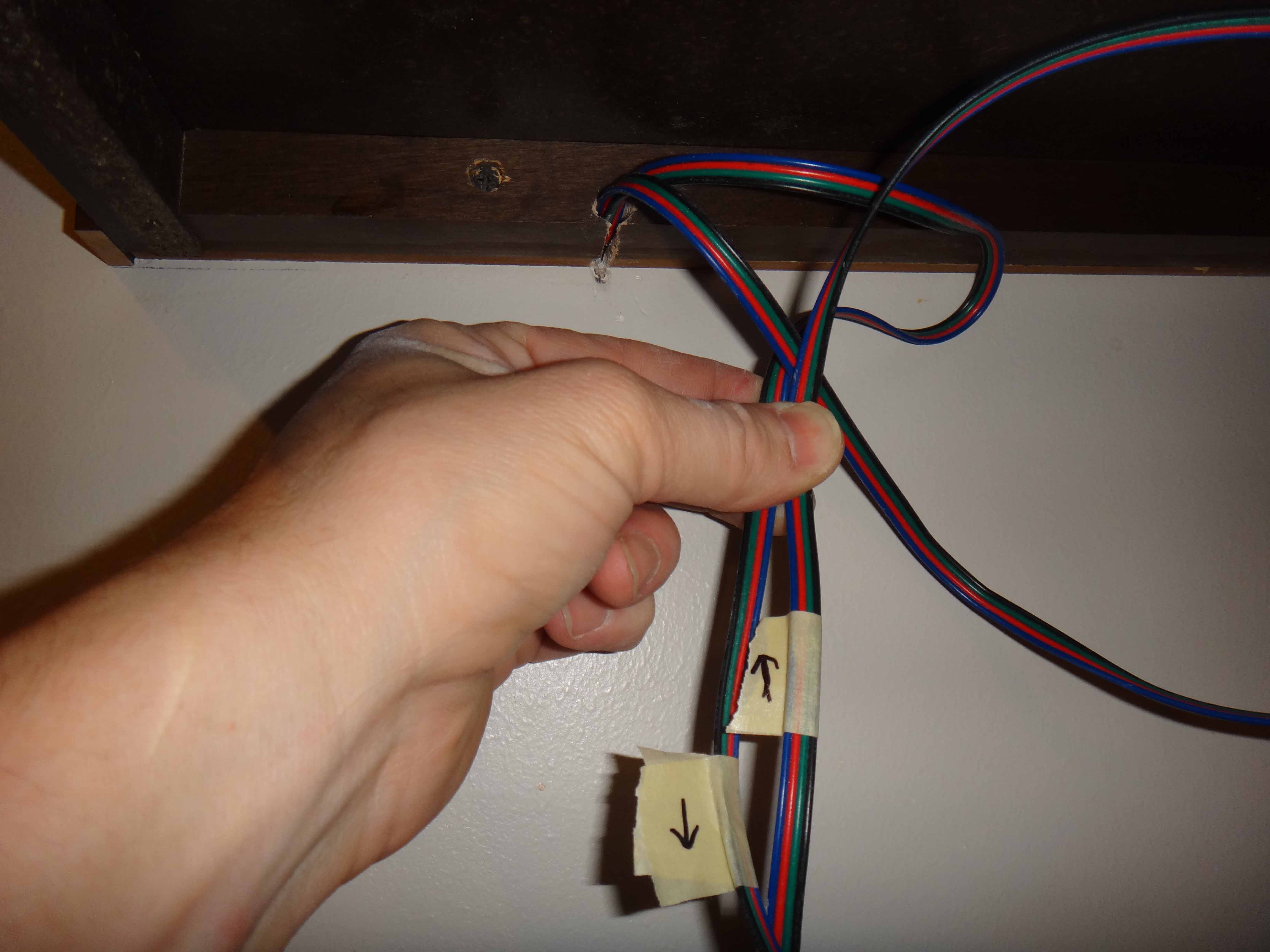
Note that direction is important for these LEDs. Thus, I was careful about drawing arrows on the cable, as it would be easy to lose your bearing once the cable was in the wall.
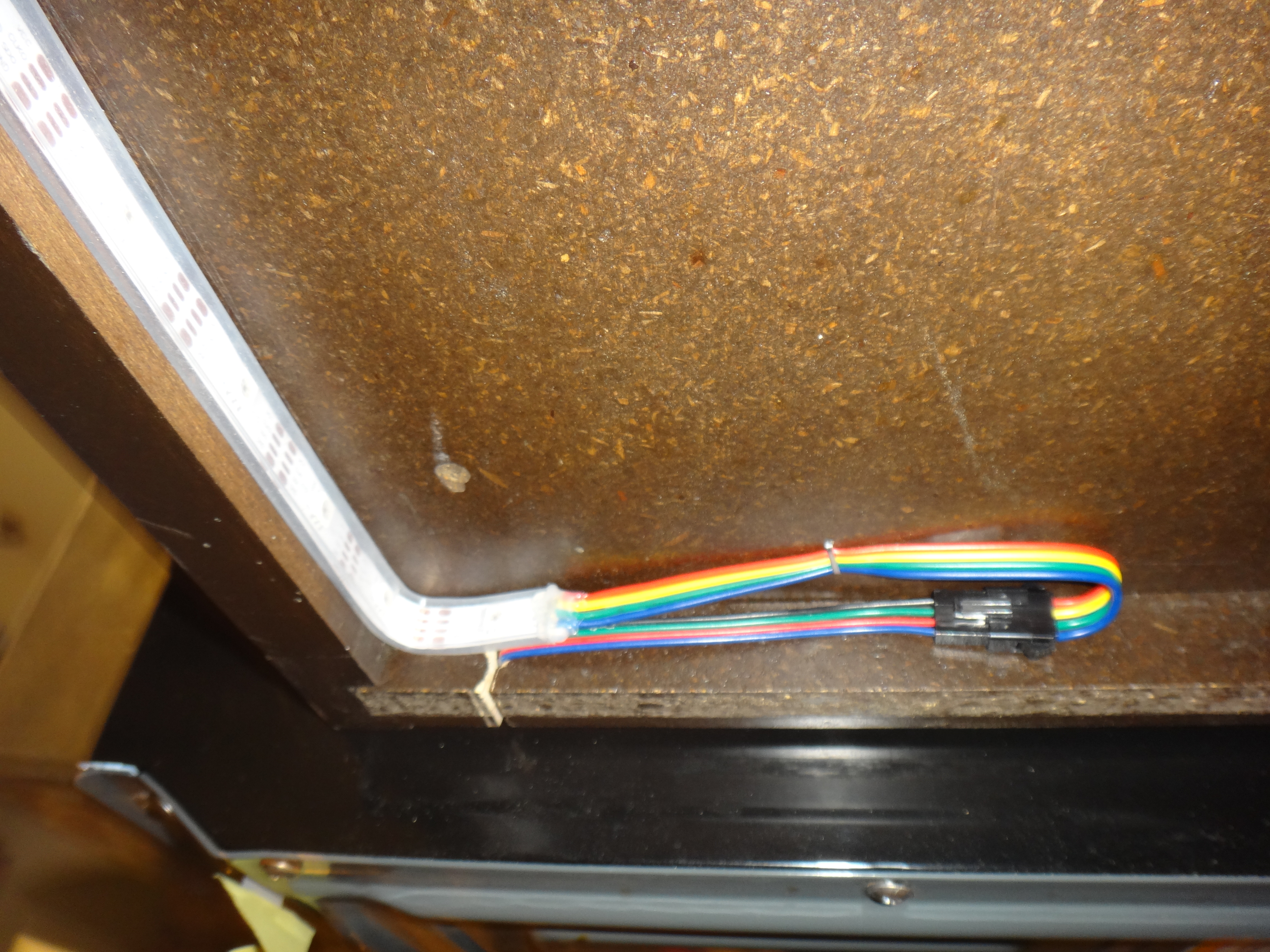
Now I was ready for the fun part to begin. Again, to make this clean and temporary, I decided to use the same 2.5mm Pitch 4-Pin JST SM Connectors that came on my LEDs, along with a PA-20 Universal Wire Terminal Crimping Tool to crimp them. My install required 14 connections (male and female), with 4 pins and 4 sockets each. That was a lot of crimping! A bad crimp somewhere is another possible culprit of my occasional glitches. Here’s a sample of LED interconnect wiring using the JST connectors.
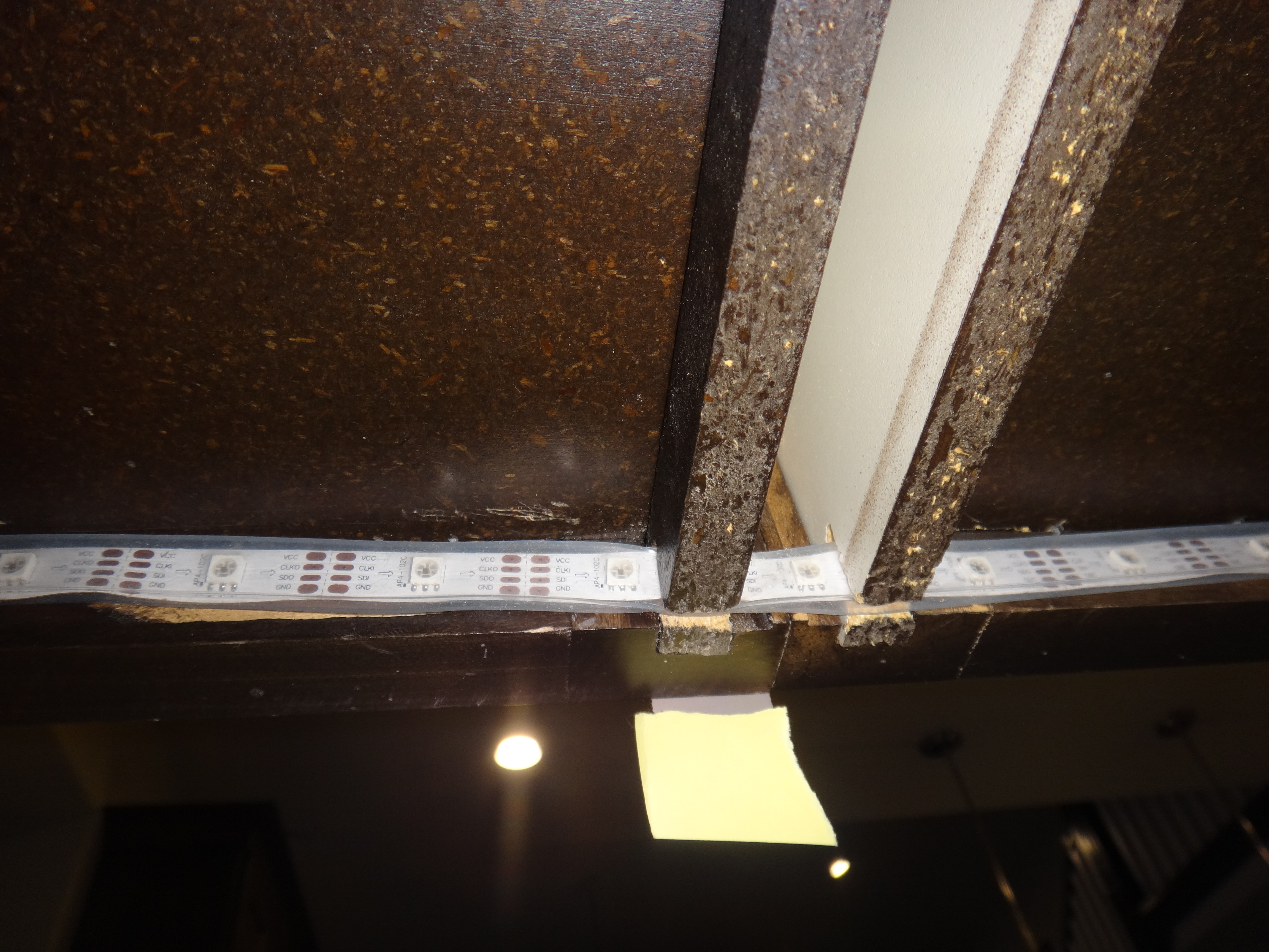
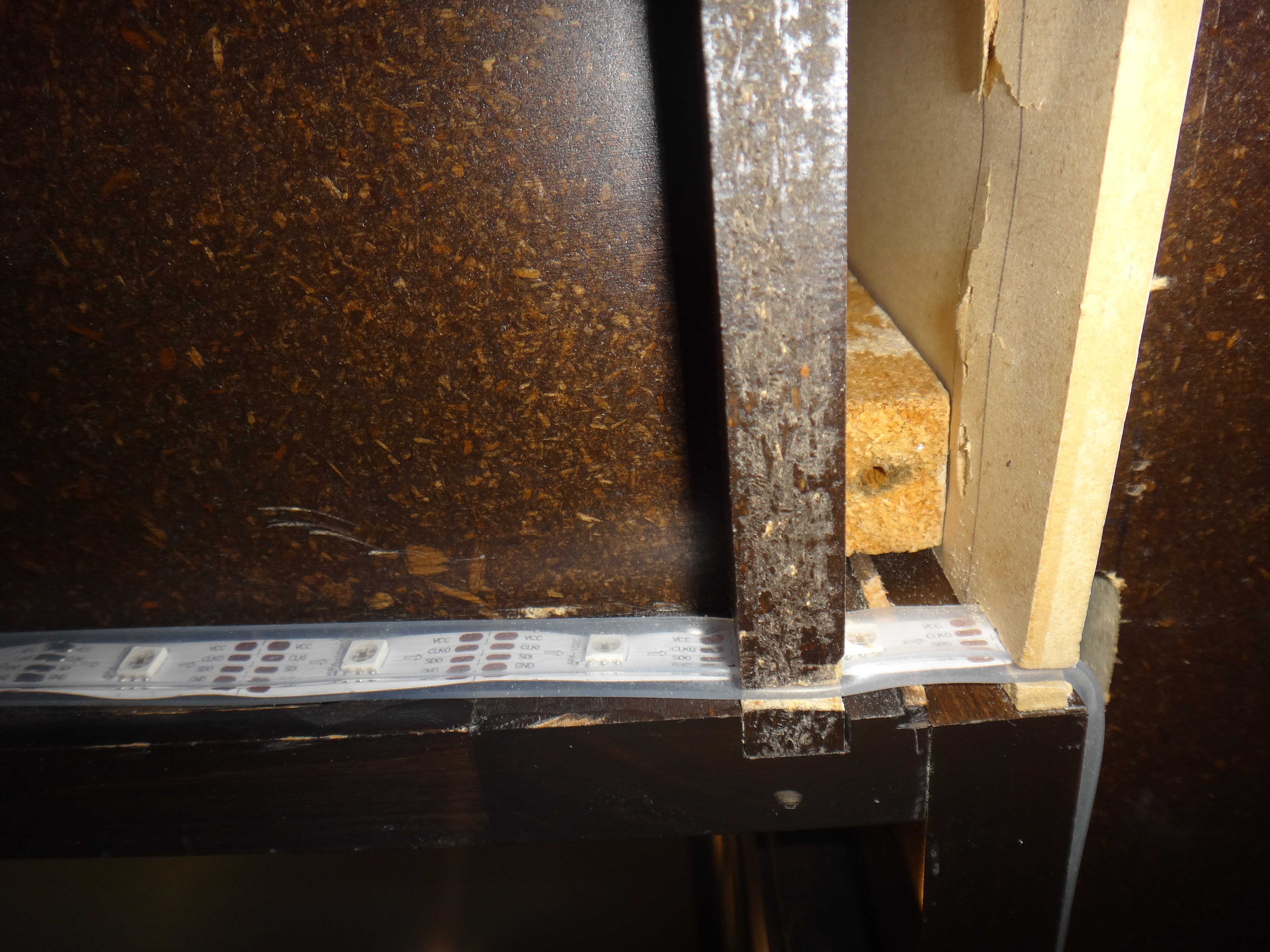
Finally, I was able to start installing the LEDs on the perimeter of each section of cabinets. On the top, I just followed the inside of the crown moulding. On the bottom, I just followed the inner trim. Where two cabinets joined together, I had to use a hack saw blade to carefully clear a path for the LEDs. Here are a few samples looking up from underneath the cabinets:
That wraps up the LED install. Next up is how to control them!